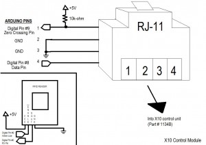
In this example, I control 1 device (on X10 circuit A, device 1). I initally turn the device off. When the RFID tag I am looking for is read, I turn the lights on. Next time that tag is read, I turn the lights off. I acknowledge various changes by providing feedback to the user via blinking LEDs and serial comms to the PC. I use the free SSH/telnet client PuTTY, found here.
Now, for the code…
——————————————–
#include x10.h
#include x10constants.h
// RFID reader variables
#define TAG_LEN 12
char tag[12] = {‘0’, ‘F’, ‘0’, ‘3’, ‘0’, ‘3’, ‘7’, ‘1’, ‘8’, ‘5’};
char code[12];
int bytesread = 0;
int ledPin = 13; // Connect LED to pin 13
int rfidPin = 2; // RFID enable pin connected to digital pin 2
int val=0;
// X10 Control unit variables
int zcPin = 9;
int dataPin = 8;
int repeat = 1;
boolean LightsOn = false;
// Declare and instance of an X10 control module
x10 myHouse = x10(zcPin, dataPin); // 9 is 0xing pin; 8 is data pin
void setup()
{
// Begin serial comms with the PC
Serial.begin(2400); // RFID reader SOUT pin connected to Serial RX pin at 2400bps
// X10 Module
myHouse.write(A, ALL_UNITS_OFF, repeat);
pinMode(zcPin,INPUT);
pinMode(dataPin,OUTPUT);
// RFID
pinMode(rfidPin,OUTPUT); // Set digital pin 2 as OUTPUT to connect it to the RFID /ENABLE pin
pinMode(ledPin,OUTPUT); // Set ledPin to output
digitalWrite(rfidPin, LOW); // Activate the RFID reader
blink(); // All variables are set, notify user ready to operate
Serial.println(“Setup complete, all lights OFF.”);
}
void loop()
{
if(Serial.available() > 0)
{ // if data available from reader
if((val = Serial.read()) == 10)
{ // check for header
bytesread = 0;
while(bytesread<10)
{ // read 10 digit code
if( Serial.available() > 0)
{
val = Serial.read();
if((val == 10)||(val == 13))
{ // if header or stop bytes before the 10 digit reading
break; // stop reading
}
code[bytesread] = val; // add the digit
bytesread++; // ready to read next digit
}
}
if(bytesread >= 10)
{ // if 10 digit read is complete
Serial.flush(); // clear “ghost” readings of the same RFID
if(strcmp(code, tag) == 0) // Does the tag read match the one we are looking for
{
Serial.print(“Tag matches: “); // Yes
Serial.println(code);
if (LightsOn == false) // If lights are off, turn them on.
{
blink();
myHouse.write(A, UNIT_1, repeat);
myHouse.write(A, ON, repeat);
LightsOn = true;
Serial.println(“Lights ON.”);
}
else // Lights are on, so turn them off
{
blink();
myHouse.write(A, UNIT_1, repeat);
myHouse.write(A, OFF, repeat);
LightsOn = false;
Serial.println(“Lights OFF.”);
}
digitalWrite(rfidPin, HIGH); // Pause the reader after a read cycle to reduce multiple
delay(3000); // readings from the same tag.
Serial.flush();
digitalWrite(rfidPin, LOW);
}
else // Tag read is not the one we’re looking for.
{
Serial.print(code);
Serial.println(” does not match”);
digitalWrite(rfidPin, HIGH); // Flush accidental multiple readings
delay(3000);
Serial.flush();
digitalWrite(rfidPin, LOW);
}
}
bytesread = 0; // clear system and prepare for next cycle
delay(500); // wait for a second
}
}
}
/***************************
* Function: blink
* Blink the LED to ack actions
****************************/
void blink()
{
digitalWrite(13,HIGH);
delay(1000);
digitalWrite(13,LOW);
}


Pingback: Review: X10 Home Automation with Arduino « Arduinian Tales